Engineering Projects
Here is a list of some current and past engineering projects I was a part of or led. The skills used in these projects cover many aspects of engineering, including design, coordination, and technical writing
Front Brake Caliper
For the CWRU Motorsports 2026 car, I am designing the front brake calipers. This design is still in progress and not finalized as of October. A major change implemented this year was moving the seals off of the pistons and into the actual caliper, allowing for the width of the caliper to decrease, helping reduce weight. Compression springs will also be added to the slide pins to assist with the retraction of the piston and pads when the brakes are released. The inlet port and bleeder port will be designed to be angled upward, allowing for the brakes to be bled on the car, reducing the time that it takes to perform this maintenance, but it is dependent on clearance with the tire rim.


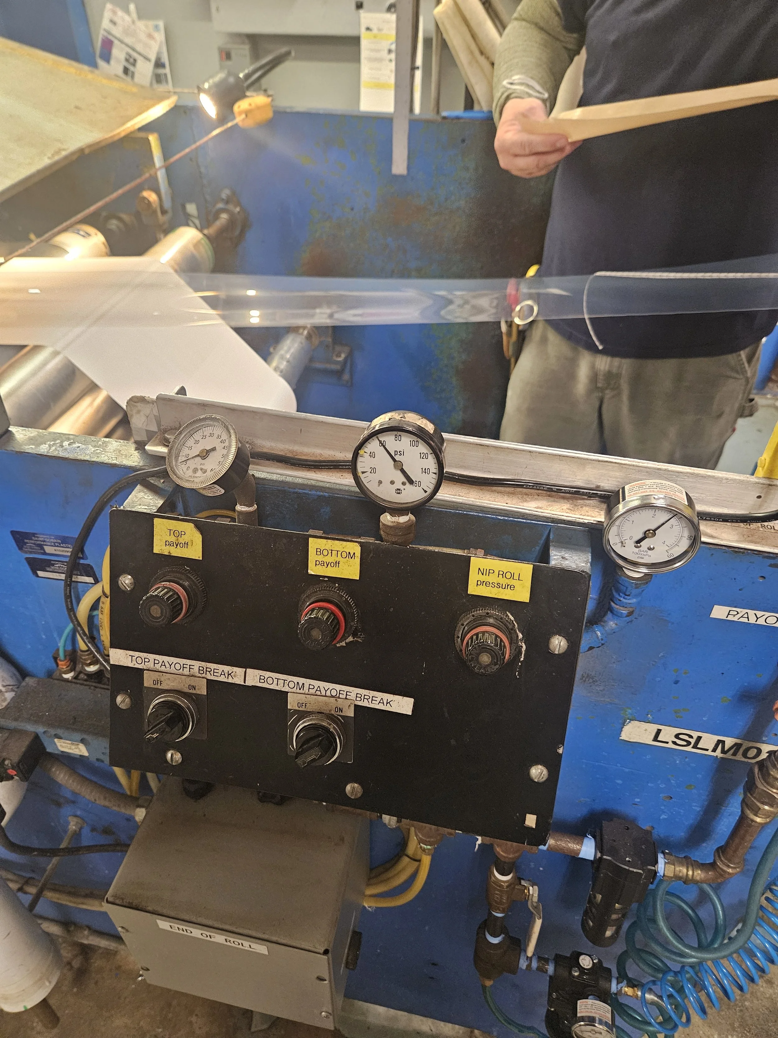
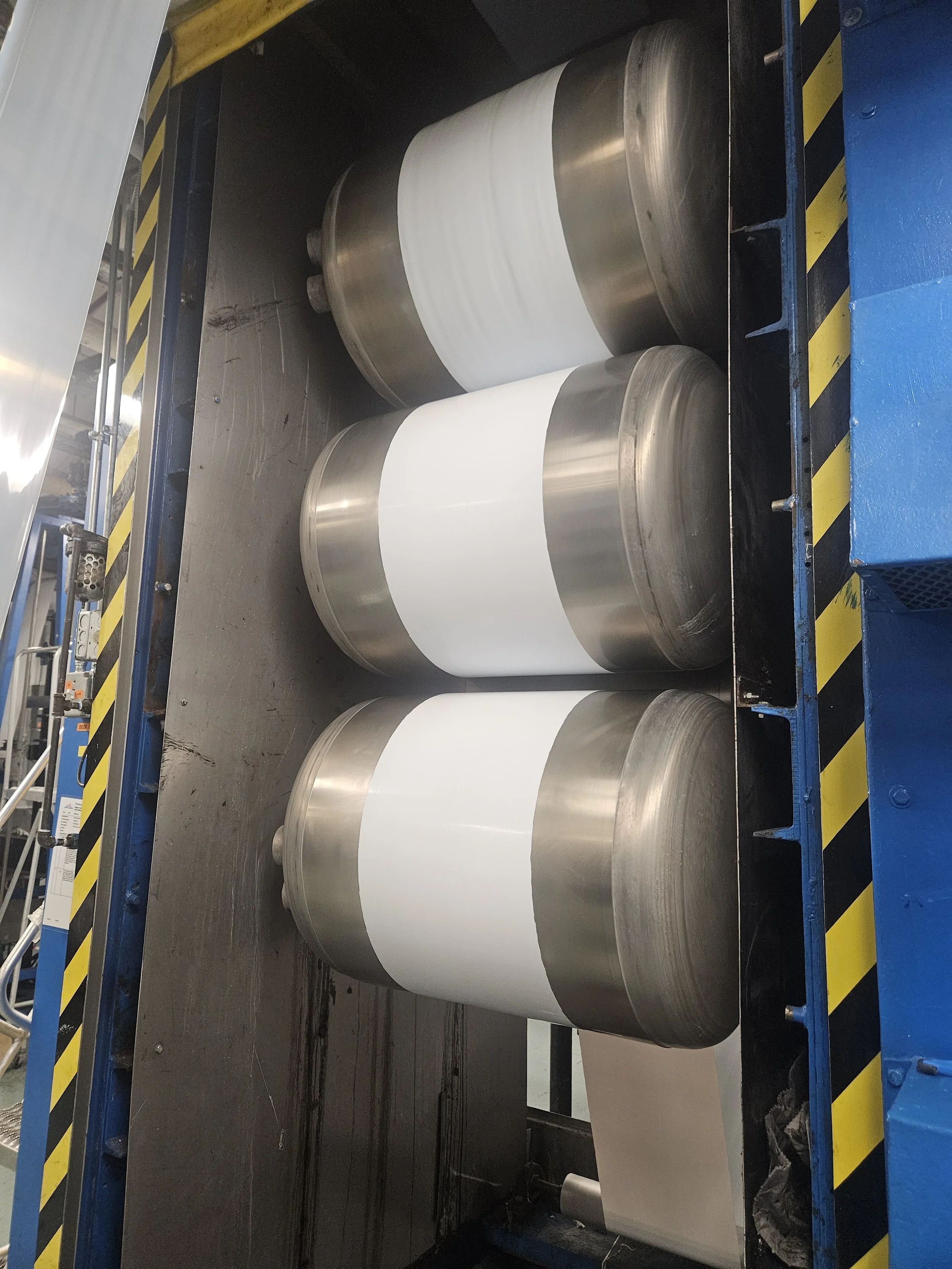
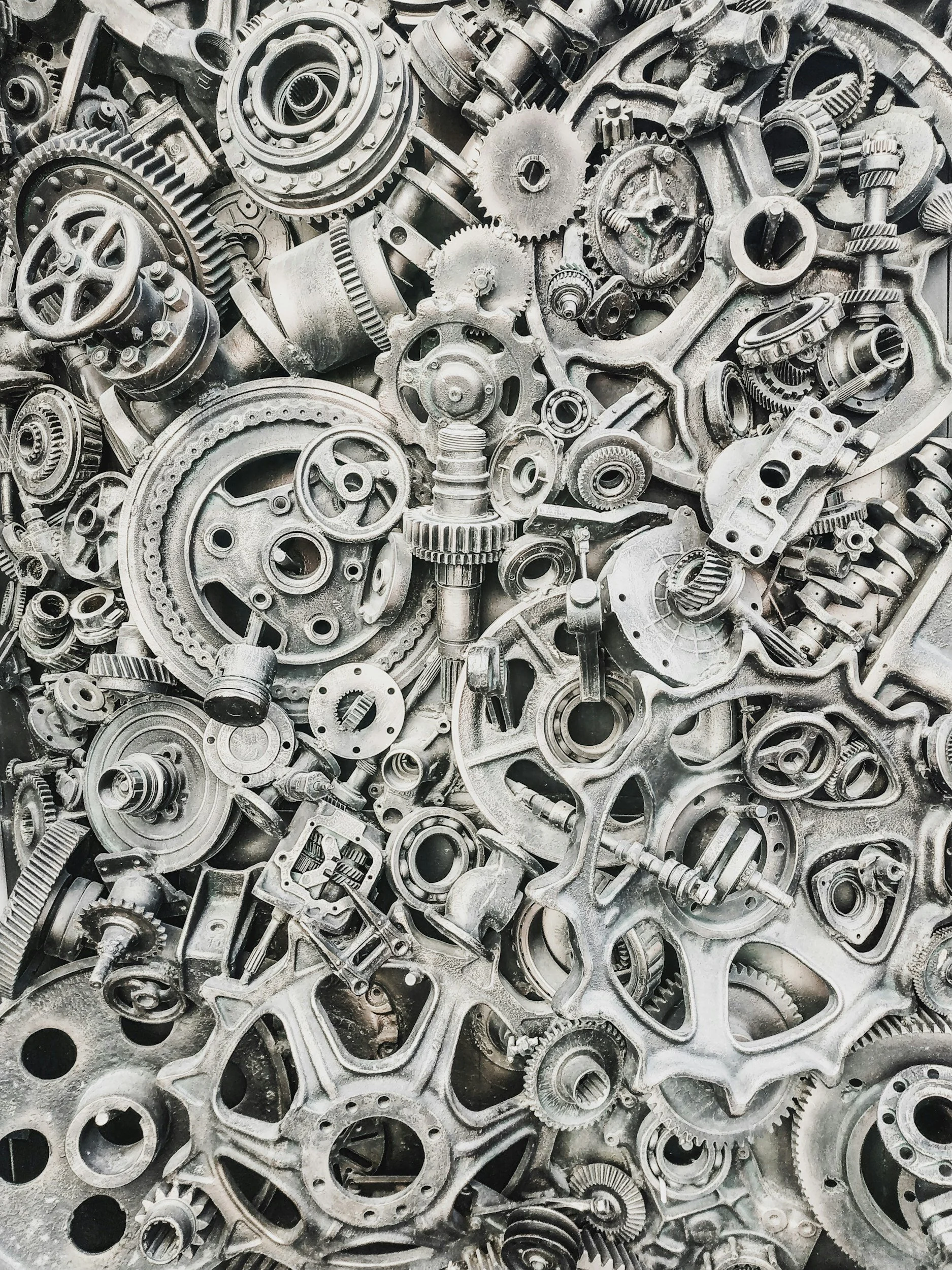
Trial and Production Runs
During my time at Saint-Gobain, I oversaw multiple trial and production runs for new and existing PTFE and other silicone products. During these trials, samples were taken and experimented with, and machine settings were adjusted to ensure the final material was within tolerance. I worked directly with quality technicians and operators, reviewing any defects in material and developing solutions in real time. I took notes to create written reports to document the design and production process changes. During my time, two test products completed production-sized runs that were shipped out to customers, and I helped develop the calibrations on a newer machine to produce an additional two products.
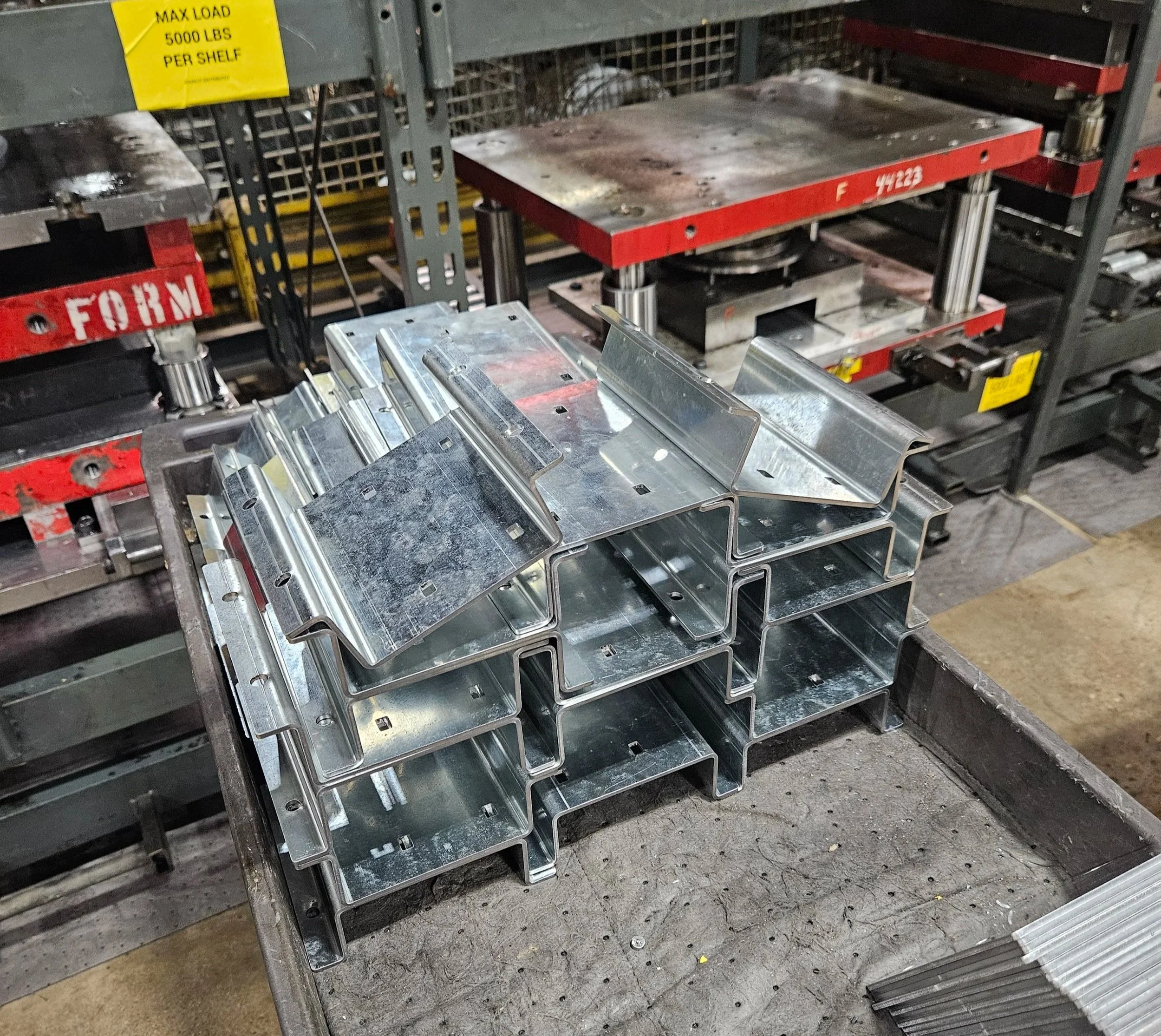
Production Modeling
At Morrison Products, I utilized my SolidWorks skills to design multiple parts that aided in the manufacturing process. The top image depicts a V-block spinning assembly station that was used in the assembly line for blower fans. During my internship, production wanted to create an additional assembly line, which required an extra stand. Taking dimensions from the two existing production lines, I modeled an identical assembly area using Sheet metal tools and then fabricated it with a laser cutter and press brake.


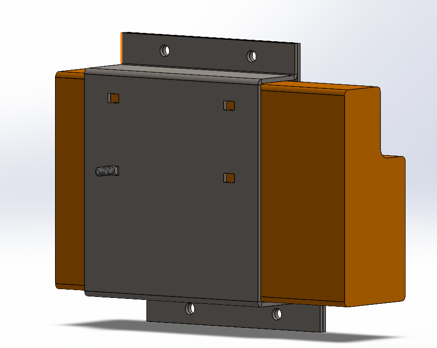
Weld Cell Mounting Fixture
These two images show a mounting fixture I designed for a new robotic welding machine. In designing this mount, many challenges presented themselves as care was taken to ensure:
Force was evenly distributed across the bottom ring of the mount, maintaining contact with the top line,
The operator would be able to align the fan blades and the top plate correctly
All weld locations were accessible for the laser.
In the process of designing both of these parts, communication with operators and other engineers was crucial to ensuring the final product was effective and easily usable by the operator. Dowel pins were used inside the top plate’s center to provide contact across the whole assembly.
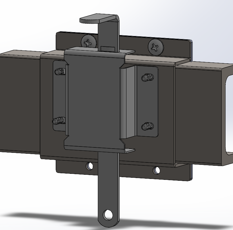
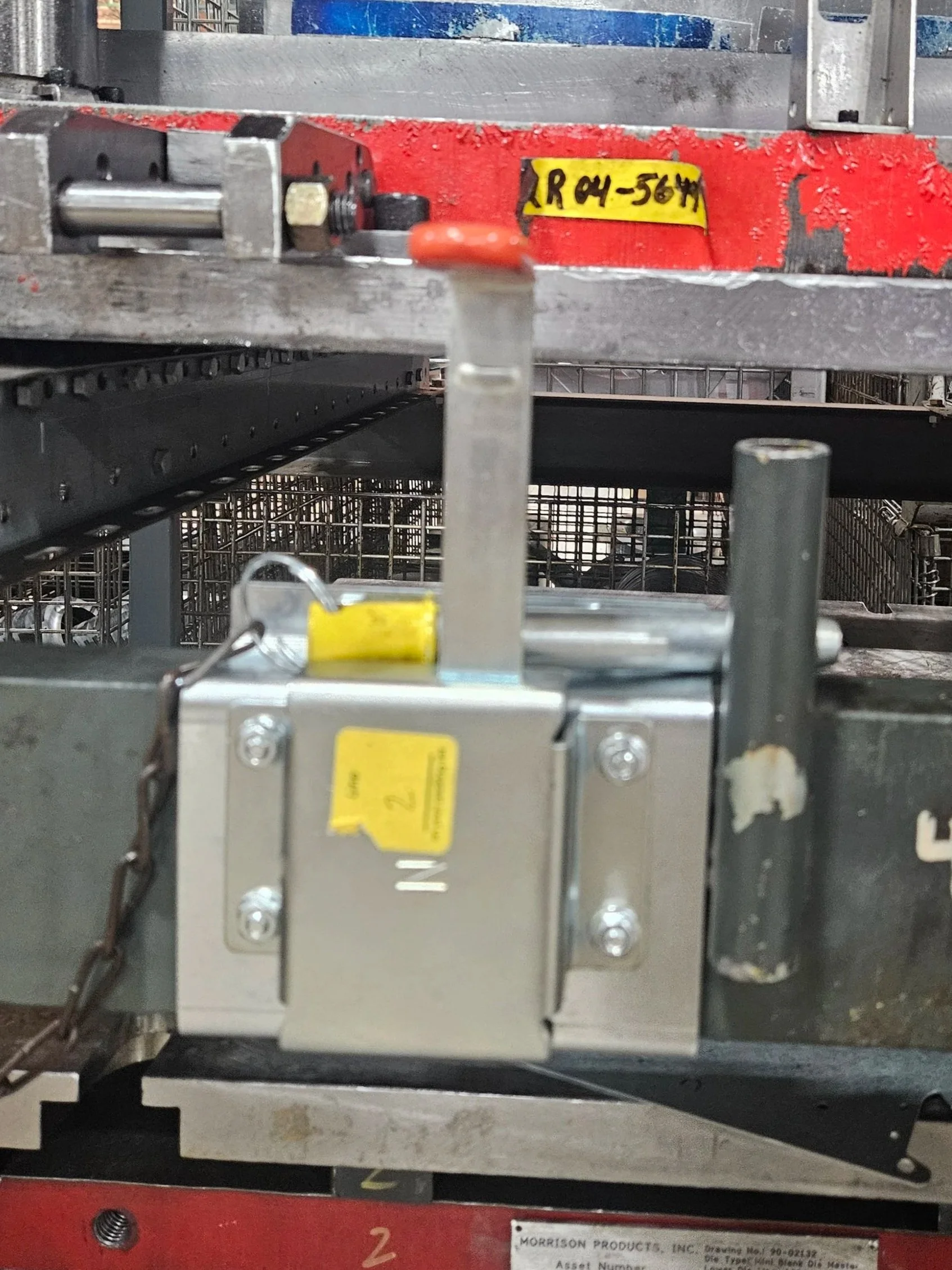
Production Modeling
The four images to the right were a latch design I created to prevent dies stored in racks from falling off. Previously, a pin system was utilized, and while effective, operators would frequently dent them when moving dies onto die carts. These pins were welded onto the actual storage racks, so replacement of the bent pins and pin holes took excessive time. My solution was to bolt two plates to the crossbar with a barn latch attached to the front plate through 4 additional bolts. This eliminated the need to remember where to place the loose pin after removal. It also gave a better visual aid of the latch being in the way with the orange handle. The replacement of the latches was also simpler, as only four nuts needed to be taken off to remove the bent latch, and the actual plates could stay on.

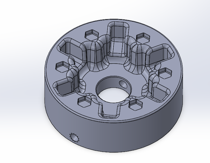
Fan Hub Mounting Fixture
Shown is a mounting block I designed to attach a back plate and stiffener in one assembly station. For this, 6 bolts would be preplaced before fitting the back plate and hub together. This would allow all bolts to be set, limiting the struggle of locating the hole for each piece. The attached hub and backplate would then be flipped over, with the stiffener attached on the other side. The large cutouts allowed for bolts to sit in the mount when attaching the stiffener, keeping the whole assembly still. This design was reviewed with operators, listening to their feedback and adapting accordingly.